Need help designing an airbox

The place for all technical car discussions. If you haven't already, read our Disclaimer first!

Moderator: The Mod Squad

Postby touge_ae101 » Sun Feb 20, 2011 1:49 pm

ok since ms paint pics are always the best at explaining shit, i have got a beaut right here!

Image

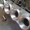
idea is to make a airbox that can squeeze between the engine and the battery without having to relocate it. best thing would be to get a bit skilled up TIG welding or get freindly with a fabricator and swing a few boxes of beers their way.
way to do it is to measure up the space you have between the battery and the coil packs. (could rotate battery a bit to give extra room) and then go down to your local parts store and give them a challenge that only their smartest 17yr old pimply faced wanna be mechanic will be able to sort for you - if your lucky that is. anyway go through their stock of panel filters until you find the biggest one possible that will fit into that space. then start designing your airbox around that. cardboard will show you the best way of figuring out dimensions and constraints or the use of CAD also helps as a mock up tool. from there it is simple. keep biggest volume of 'filtered' air available close to the engine, this will give your car good response and not lose any torque. i would say this will give a much better result than a factory box (so up yours to mr toyota and their millions of $$ of research!:wink: )
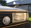
keep the front of the filter enclosed and bring it down to a opening that you can fit the biggest-bit-of-flexi-hose-you-can-find over and jam this right in the front bumper where it will get plenty of fresh air (fog light perhaps)

this will make your engine bay look bling and be very practical in making moar power! even get it made out of alloy for lightweightness if you can find someone to weld it for you. only thing you may want to do is get some heat sheild to stop the hot air from extractors warming up the airbox too much as both alloy and stainless conduct heat quite well.

i've been pondering this design for a while and i got the idea off a TOM's carbon fibre intake thingy i saw on a touring car with a silvertop in it. it looks like they are about the same dimensions so you could sell to 4age people too.
so if you actually develop an airbox, i'm sure there could be people out there willing to pay the $$$ for it if its dyno proven.

if i didn't already have a mac daddy airbox i would of done this by now.

edit: oh btw blue is filter, orientated as a vertical rectangular shaped non-descript ms paint object, and red is the outline of the box (also badly drawn) but hope you can see what i mean :P
Last edited by touge_ae101 on Sun Feb 20, 2011 1:51 pm, edited 1 time in total.
User avatar
touge_ae101
Toyspeed Member
 
Posts: 1730
Joined: Mon Sep 14, 2009 7:23 pm
Location: Palmerston North

Postby Bling » Sun Feb 20, 2011 1:49 pm

Unless you seal the pod completely from the engine bay with good ducting to it you're wasting your time and money to get no gains. Ducting to the factory box with a good filter will be as good as any pod filter i'm sure. Just not as cool looking / sounding so I guess it won't be an option. I've had open trumpets, pod filter and factory intake with K&N filter. I settled on the factory setup with good filter.
User avatar
Bling
** Moderator **
 
Posts: 15990
Joined: Mon Dec 22, 2003 9:02 pm
Location: Quake City

Postby Dragger_Dan » Sun Feb 20, 2011 2:09 pm

http://www.pipercross.net/fastroad/products_universal.asp

This? I have a feeling they cost a fortune, but the design makes some amount of sense. I think that BNT Automotive stocks them.
Dragger_Dan
 

Postby nz_climber » Sun Feb 20, 2011 4:05 pm

K&N do a similar thing. Surprised not more people use them, would be a lot simpler than building a box

http://www.knfilters.com/universal/apollo.htm

Plus with either of these options you get a good quality filter (unlike most of the pod filters you get from supercheap etc)
nz_climber
Toyspeed Member
 
Posts: 322
Joined: Sat Dec 20, 2003 10:29 pm
Location: Bulls

Postby touge_ae101 » Sun Feb 20, 2011 4:52 pm

ok so MS paint drawings are gay so i got bored and did this.

Image
Image
User avatar
touge_ae101
Toyspeed Member
 
Posts: 1730
Joined: Mon Sep 14, 2009 7:23 pm
Location: Palmerston North

Postby Bling » Sun Feb 20, 2011 4:58 pm

That looks pretty sweet. I still think a standard airbox with a bigger duct to cold air into it will do the same job. All comes down to the bling I guess. They do the same job, they just look different and cost a lot different amounts to make. Don't forget to add a placebo sticker on the side. :lol: His money though, everyone wastes it in different ways. :oops:
User avatar
Bling
** Moderator **
 
Posts: 15990
Joined: Mon Dec 22, 2003 9:02 pm
Location: Quake City

Postby touge_ae101 » Sun Feb 20, 2011 5:12 pm

yeah possibly this one would provide a large volume of air on the engine side of the filter much like the ARC chamber type design so could have small improvements over stock.

by the looks of that engine bay, the dimensions looks quite similar to a blacktop. so if someone wants to buy my airbox, i'll could start developing one like this so it can be fitted with the battery in the stock location.

at a guess, it would cost me about $350 bux to make this labour and materials + panel filter included. would need to sell a few of them to make it worth while but definately a lot better money than what you pay for a ARC airbox + expansion chamber.
User avatar
touge_ae101
Toyspeed Member
 
Posts: 1730
Joined: Mon Sep 14, 2009 7:23 pm
Location: Palmerston North

Postby RomanV » Sun Feb 20, 2011 8:48 pm

nzhogrider wrote:Often refered to as a second-hole mod.


I thought that's what you do if the first hole is too big?
User avatar
RomanV
Toyspeed Member
 
Posts: 4915
Joined: Wed Aug 13, 2003 12:17 am
Location: West Auckland

Postby touge_ae101 » Sun Feb 20, 2011 10:05 pm

RomanV wrote:
nzhogrider wrote:Often refered to as a second-hole mod.


I thought that's what you do if the first hole is too big?


:lol: irl rofl
User avatar
touge_ae101
Toyspeed Member
 
Posts: 1730
Joined: Mon Sep 14, 2009 7:23 pm
Location: Palmerston North

Postby nzhogrider » Sun Feb 20, 2011 10:27 pm

Hey touge_ae101, your drawings are sweet. Could I offer some sweet idea for your airbox design? How about instead of mounting the panel filter in the absolute vertical plain, try angling it back from the bottom to the top, so using pythagoras theorem you can see you'll either minimise the size of the airbox for the same size panel filter, or maximise the size of the panel filter for the same size airbox.
nzhogrider
Toyspeed Member
 
Posts: 118
Joined: Fri Apr 01, 2005 8:52 pm
Location: Manawatu

Postby cat007 » Sun Feb 20, 2011 10:40 pm

Would be very keen to know if anyone has any dyno results, on the same day and dyno, where they used a pod in the engine bay and then with a 'cold air box'

You'd need the bonnet down for the tests to be worthwhile.

Probably a long shot though....
1:15.4 around Pukekohe
13.63 @ 169kmph at Meremere
Fastest MK3 at Suprafest 08
1G-GTE - Stinger 4424, T04B 60-1, 440cc injectors - 240rwkw @ 16psi
User avatar
cat007
Toyspeed Member
 
Posts: 3577
Joined: Sun Sep 01, 2002 7:29 pm

Postby touge_ae101 » Sun Feb 20, 2011 10:40 pm

nzhogrider wrote:Hey touge_ae101, your drawings are sweet. Could I offer some sweet idea for your airbox design? How about instead of mounting the panel filter in the absolute vertical plain, try angling it back from the bottom to the top, so using pythagoras theorem you can see you'll either minimise the size of the airbox for the same size panel filter, or maximise the size of the panel filter for the same size airbox.


yeah this i have thought about but the problem is if the airflow isn't perpindicular to the perferations in the air filter, it would actually disrupt airflow.

ms paint to the rescue again!
Image

i figured this out after i started making my one then looked at it and blew some compressed air through the filter to feel at which angles it actually went through easiest and ended up changing my filter so that it is curved. only gained about 10mm of length by curving it so not sure if it is worth changing the orientation.
User avatar
touge_ae101
Toyspeed Member
 
Posts: 1730
Joined: Mon Sep 14, 2009 7:23 pm
Location: Palmerston North

Postby siren676 » Sun Feb 20, 2011 11:01 pm

Dude your design and cad skills are very impressive.

If you are able to make this product I will definately buy it. I will give my engine bay a quick measure up in the morning and you can compare it to your 4age one.

Will this design run into the problem of forcing air into the engine and possibly making it run lean?
1998 5dr Glanza V Replica - 5E-FHE powered

1990 Mazda MX5 NA6C drift build - Met a wall 2/5/15
User avatar
siren676
Toyspeed Member
 
Posts: 1015
Joined: Sun Jun 13, 2010 1:47 pm
Location: South Auckland

Postby nzhogrider » Sun Feb 20, 2011 11:01 pm

You could get a filter that suits so that the 'flutes' are in the vertical plain instead of the horizontal as you have drawn it, so that way the airflow is always presented in the same direction as the fluting of the filter. Did you try weighing up the benefits of the overall efficiency offered by the increase of panel area vs. the slight disruption to the airflow due to the angle of the panel? Would be worthwhile if the increased area more than made up for the slight disruption wouldn't it? Besides, the fct that the filter element is fluted in the first place means that the airflow is always being introduced at some angle anyway doesn't it? Rhys if you are going to build a new airbox would you consider emulating the designs of the K&N and Pipercross items already menntioned above? Surely the cone stlye filter offers the best overall area to cross sectional size ratio around, coupled with being enclosed to isolate it from hot air in the engine bay with the added bonus of the purpose built cold air feed, it's got to be close to ideal.
nzhogrider
Toyspeed Member
 
Posts: 118
Joined: Fri Apr 01, 2005 8:52 pm
Location: Manawatu

Postby nzhogrider » Sun Feb 20, 2011 11:06 pm

siren676 wrote:Will this design run into the problem of forcing air into the engine and possibly making it run lean?


Um I don't know where you got this idea from, but unless the air is sneaking around the MAP or MAF sensor and then into your engine then you will be fine. The air being under pressure or not wont upset your air:fuel ratio since it is set by the computer due to measured parameters; the main one of which is the amount of air entering your engine via the MAP or MAF sensor. So unless you are bypassing this measurement then nothing will upset the ratios.
nzhogrider
Toyspeed Member
 
Posts: 118
Joined: Fri Apr 01, 2005 8:52 pm
Location: Manawatu

Postby siren676 » Sun Feb 20, 2011 11:07 pm

cat007 wrote:Would be very keen to know if anyone has any dyno results, on the same day and dyno, where they used a pod in the engine bay and then with a 'cold air box'

You'd need the bonnet down for the tests to be worthwhile.

Probably a long shot though....

If the design gets put in to production i will volunteer my car (and wallet) to be the guinea pig as there is a dyno just down the road from my place
1998 5dr Glanza V Replica - 5E-FHE powered

1990 Mazda MX5 NA6C drift build - Met a wall 2/5/15
User avatar
siren676
Toyspeed Member
 
Posts: 1015
Joined: Sun Jun 13, 2010 1:47 pm
Location: South Auckland

Postby siren676 » Sun Feb 20, 2011 11:08 pm

nzhogrider wrote:
siren676 wrote:Will this design run into the problem of forcing air into the engine and possibly making it run lean?


Um I don't know where you got this idea from, but unless the air is sneaking around the MAP or MAF sensor and then into your engine then you will be fine. The air being under pressure or not wont upset your air:fuel ratio since it is set by the computer due to measured parameters; the main one of which is the amount of air entering your engine via the MAP or MAF sensor. So unless you are bypassing this measurement then nothing will upset the ratios.
So it will be almost like a natural turbo/supercharger?
1998 5dr Glanza V Replica - 5E-FHE powered

1990 Mazda MX5 NA6C drift build - Met a wall 2/5/15
User avatar
siren676
Toyspeed Member
 
Posts: 1015
Joined: Sun Jun 13, 2010 1:47 pm
Location: South Auckland

Postby Bling » Sun Feb 20, 2011 11:12 pm

Unless you take all the air in front on the car, funnel it into a 4" pipe, I doub't you'd see boost :lol: :lol:
User avatar
Bling
** Moderator **
 
Posts: 15990
Joined: Mon Dec 22, 2003 9:02 pm
Location: Quake City

Postby siren676 » Sun Feb 20, 2011 11:18 pm

wow your car must be pretty powerful to have a 4" throttle body. I think my current throttle is only 45mm
1998 5dr Glanza V Replica - 5E-FHE powered

1990 Mazda MX5 NA6C drift build - Met a wall 2/5/15
User avatar
siren676
Toyspeed Member
 
Posts: 1015
Joined: Sun Jun 13, 2010 1:47 pm
Location: South Auckland

Postby Bling » Sun Feb 20, 2011 11:23 pm

So you have a 45mm pipe all the way to the throttle body? :lol:

I said pipe not throttle body. I do have quads though :wink:
User avatar
Bling
** Moderator **
 
Posts: 15990
Joined: Mon Dec 22, 2003 9:02 pm
Location: Quake City

PreviousNext

Return to Tech Questions

Who is online

Users browsing this forum: No registered users and 23 guests