MR2 Radiator/airflow mods

General discussions on all non technical car related topics

Moderator: The Mod Squad

Postby RomanV » Tue Nov 29, 2005 2:09 pm

Well I suppose it makes sense that the lowest pressure would be at the base of the rear windscreen.

I dont know about the stock spoiler downforce though, however I heard that it dramatically improves stability when driving with cross winds.

Perhaps I should restart my MR2 3d wind tunnel model with an AW11, it would be a lot easier to model. :P 8)
User avatar
RomanV
Toyspeed Member
 
Posts: 4915
Joined: Wed Aug 13, 2003 12:17 am
Location: West Auckland

Postby Mr Revhead » Tue Nov 29, 2005 2:12 pm

please do, coz i cant get the %&*$ thing to work.
Being the subject of E-whinges since 2004 8)

http://www.centralmotorsport.org.nz/home

Image
User avatar
Mr Revhead
SECURITY!
 
Posts: 24635
Joined: Tue Jan 20, 2004 4:06 pm
Location: Nelson

Postby RomanV » Tue Nov 29, 2005 2:19 pm

Its probably for the better....

I probably know how to use 20% of its capabilities, and it $&#$% me off incredibly, every time I try to do something with it. :lol:
User avatar
RomanV
Toyspeed Member
 
Posts: 4915
Joined: Wed Aug 13, 2003 12:17 am
Location: West Auckland

Postby Malcolm » Tue Nov 29, 2005 11:43 pm

interesting little chat you're having here.
just so you know, the intention is to keep the spare, and most of the frunk space. I can currently fit a space saver tyre easily, and I wont be coming anywhere near it. I did some more work on it today, but I really can't get good welds with my shitty arc welder (and my shitty welding skills) so I will probably have to get someone else to finish off the welding. Tomorrow I might start on the bonnet.
User avatar
Malcolm
Toyspeed Member
 
Posts: 4631
Joined: Tue May 14, 2002 1:01 am
Location: Auckland

Postby Malcolm » Wed Nov 30, 2005 11:56 pm

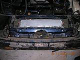
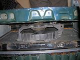
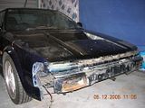
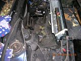
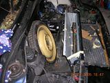
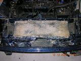
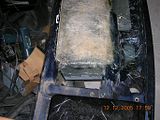
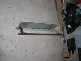
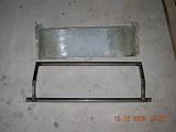
here's some pictures of what I did yesterday.

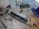
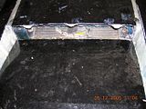
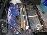
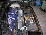
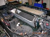
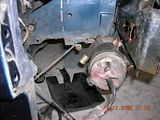
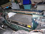
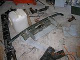
this shroud will be sealed to the radiator by putting some rubber vacuum line around it's bottom edge, and there will be a matching piece on the bulkhead which it will also seal against. pics (click to enlarge):

Image Image Image Image Image


Today I did a little work on the bonnet, no pics because my dad's gone to Rarotonga and taken the camera. After talking to a guy at a fibreglass shop who thought I'd be insane to try and make a fibreglass bonnet, I've opted for a simpler design. Instead of the twin vents I pictured earlier, I'm going for a single large one in the middle, and it's just going to be a modified stock one, rather than a fibreglass one. To be honest I don't think there's realistically going to be much difference in aerodynamics doing it this way rather than with two diverting the air around the cabin, and this will take me a few hours, rather than a few days to make.

I'm going to have the ducting on the bulkhead and the duct on the bonnet overlapping so the only way water will get into the frunk will be if water comes up, through the radiator, then pools on the bottom of the duct, and gets pushed over the edge into the frunk by air pressure, but there will be lots of seals so hopefully this isn't going to be likely.

With any luck a good day tomorrow should see the bonnet half done and much of the ducting finished, awaiting expert welding...
User avatar
Malcolm
Toyspeed Member
 
Posts: 4631
Joined: Tue May 14, 2002 1:01 am
Location: Auckland

Postby RomanV » Thu Dec 01, 2005 12:55 am

cool, cant wait to see some more pics. 8)

And the AW11 frunk seems tiny compared to the SW20 one!
User avatar
RomanV
Toyspeed Member
 
Posts: 4915
Joined: Wed Aug 13, 2003 12:17 am
Location: West Auckland

Postby Malcolm » Thu Dec 01, 2005 11:35 pm

alright, made some reasonable progress today
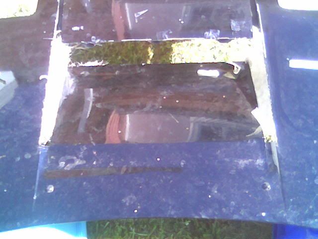
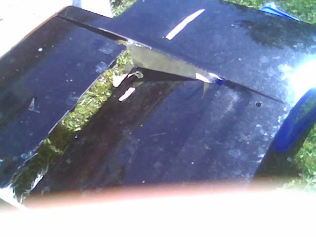
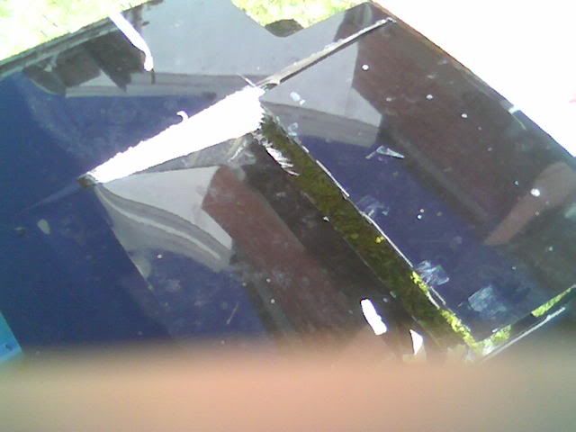
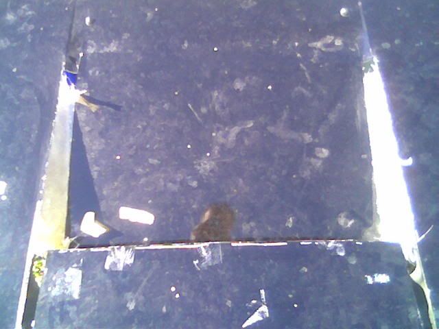
first thing I did was cut out the little (inch wide) angled strips that run up the bonnet, on either side of the recess section, then I folded the vent. Last time I did this on an engine lid, the problem was that the edges folded with a nice sharp line, but the middle was more of a gradual bend. To overcome this i carefully made a very shallow cut on the back side of the bonnet where I wanted the bend - unbelievably, not only did I manage to make a shallow cut along the thin bonnet without actually cutting through, but it actually worked and made a nice, constant fold right across the vent.

on the advice of the guy at the fibreglass shop, I made cardboard formers for the sides of the vent, and wrapped them in plastic cling wrap, then taped them into place, and fibreglassed against them. Appears to have worked very well, the sides are reasonably flat and wont need ridiculous amounts of sanding + filing like the engine lid I did.
here's pics of the bonnet, sorry about the quality, they're camera phone pictures:
Image
Image
Image
Image

the front part of the bonnet, which you will notice I have also cut, will be raised up to be flush with the rest of the bonnet, rather than recessed down like it normally is.

while I was waiting for the glass on the bonnet to cure, I did some work on the bonnet catch/shroud in the pictures earlier. I filled some of the larger holes with fibreglass, and made a small glass box to go around the catch mechanism to stop air escaping out there. I did this by making the shape out of cardboard, cling wrapping it, and then glassing it. Tomorrow I will bond it to the catch.
User avatar
Malcolm
Toyspeed Member
 
Posts: 4631
Joined: Tue May 14, 2002 1:01 am
Location: Auckland

Postby vvega » Fri Dec 02, 2005 6:53 am

in short yest the fast moving air would creat lift... its how you do it

BUT

by doing this and prviding he seals it off from the underneath he will creating a vacum under the car
most noticeably at the front ....as long as he had a dam of sorts

he may find a reduction in cooling in the enginr bay as well.......

just my thoughts

v
vvega
 

Postby Boosted_162 » Fri Dec 02, 2005 12:54 pm

Your bonnet now looks suprisingly similar to my engine lid.....funny that :P
Current:
1996 KZN185 Hilux Surf
2008 Mazda2
Boosted_162
Toyspeed Member
 
Posts: 3624
Joined: Sun Sep 04, 2005 1:02 am
Location: Kaukapakapa

Postby Malcolm » Mon Dec 05, 2005 8:10 pm

made a wee bit of progress

I've done another layer of glass on the bonnet, and started on the ducting to the bonnet. I've also pretty much sealed up the shrouded section, around the latch and stuff. Did some more welding on it and burned some of the fibreglass...oops

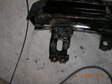
I also put some mounts into the bumper beam for what was the bottom of the radiator, by cutting them off the old radiator support beam and welding them into the slot I cut in the beam. Might take the beam to a stripper and get it acid dipped if it's not going to cost too much.

I took some pics before I started today, just of the bonnet and the latch:

Image Image Image Image
User avatar
Malcolm
Toyspeed Member
 
Posts: 4631
Joined: Tue May 14, 2002 1:01 am
Location: Auckland

Postby Malcolm » Mon Dec 05, 2005 8:15 pm

oh and you can read more here:
http://www.fasterthanjesus.net/sw11/rad.html (shameless plug)
User avatar
Malcolm
Toyspeed Member
 
Posts: 4631
Joined: Tue May 14, 2002 1:01 am
Location: Auckland

Postby Malcolm » Tue Dec 06, 2005 11:09 pm

pics from yesterday's work
Beam feet:
Image

Radiator mounted in beam
Image

Hole: it's a little wider than it needed to be, so I'm going to have to weld some little panels on either side to fill the gaps around the shourd
Image

today I did most of the ducting, just needs a bit of cleaning up and welding up. I'll just be tacking it tgoether some someone else can finish it off. Here's today's pics

Cardboard templates made for the ducting (yes it's partly a cut up steinlager box)
Image

then with a wave of my magic wand, and the cardboard becomes steel
Image

and to show how much space I will have left when it's all done:
Image

even with the spare tyre, lots of room :)
Image

at this point, the only thing I'm concerned with is the cross sectional area of the ducting at it's narrowest point. I'm still fairly sure it will flow enough, but if it doesn't I can open it up but it will make life a little trickier, or I can make another vent above the radiator, for a louvred sort of layout
User avatar
Malcolm
Toyspeed Member
 
Posts: 4631
Joined: Tue May 14, 2002 1:01 am
Location: Auckland

Postby RomanV » Tue Dec 06, 2005 11:58 pm

Aaah, so you're mounting the radiator downwards/horizontal?

I thought you were still mounting it vertically, but ducting to and from it.

interesting!

Will be interesting to see how it pans out.
User avatar
RomanV
Toyspeed Member
 
Posts: 4915
Joined: Wed Aug 13, 2003 12:17 am
Location: West Auckland

Postby Malcolm » Wed Dec 07, 2005 12:05 am

did you see any of the pictures I posted on the last 2 pages where the radiator was horizontal? :P
I prefer it this way, allows the w/a radiator to be well away from the hot engine radiator, and I'm sure there's other good reasons too :D
User avatar
Malcolm
Toyspeed Member
 
Posts: 4631
Joined: Tue May 14, 2002 1:01 am
Location: Auckland

Postby RomanV » Wed Dec 07, 2005 12:10 am

Yeah I saw the other pics, but its a bit hard to see what exactly was going on.

And I just naturally assumed it would be upright I suppose. :P
User avatar
RomanV
Toyspeed Member
 
Posts: 4915
Joined: Wed Aug 13, 2003 12:17 am
Location: West Auckland

Postby no_8wire » Wed Dec 07, 2005 9:25 am

I found the photos confusing to until I realised that the rad was horizontal... :lol:
User avatar
no_8wire
Toyspeed Member
 
Posts: 2268
Joined: Thu Dec 30, 2004 7:30 pm

Postby Malcolm » Thu Dec 08, 2005 10:44 pm

don't you hate it when you start making good progress on something, and then decide you're not happy with it?

after my last post on this I had been thinking about the flow through the duct from the radiator to the vent. At one point the cross section was getting quite small, and I was doubting whether it would flow enough to make all this hard work even worthwhile...

so I decided to make some changes. I didn't want to cut the hole any higher, because I was trying to keep the reinforcing piece that runs along the top of the bulkhead, but I decided that it just had to go.

So, here's the new hole:
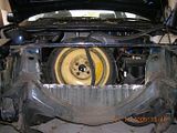
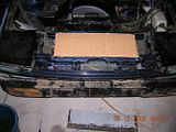
Image

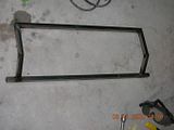
Now I had to do something about reinforcing everything, so I decided to make a frame, using 19.1mm 1.2mm wall thickness square section tubing.
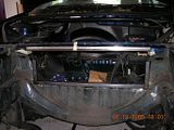
Image Image

This frame will be welded in place as shown. It will give a lot more strength to the area, and so it wont rely on welded steel panels for strength like I had originally planned. This means I could rivet or bolt the ducting on for easier removal, and I can make more use of fibreglass to minimise weight.

Anyway, because hole in the bulkhead is now much larger the shrouded piece I had made before needs modifying. I cut the top piece off, and will make a fibreglass top for it, which will seal against the frame I made.
Here's the shroud, the second picture shows where the fibreglass panel will sit
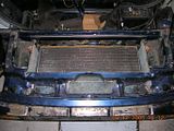
Image Image

as you can see in this picture, the area for air to flow through is now greatly increased.
Image


The other ducting I made earlier for inside the frunk will be kept, but altered to fit to the frame, rather than to be welded together.
User avatar
Malcolm
Toyspeed Member
 
Posts: 4631
Joined: Tue May 14, 2002 1:01 am
Location: Auckland

Postby Malcolm » Tue Dec 13, 2005 11:32 pm

well I've made some fairly decent progress.
Last couple of days I worked on the ducting for the new frame, which mostly meant modifying the stuff I'd alread made, but I also decided to do a lot more parts of of fibreglass. The idea is that I want everything that attaches to the frame to be removable, rather than welded in place. For this reason the back piece is now going to be rivetted to the frame, the sides are fibreglass and will be screwed or rivetted on, and all the parts that attach to the shroud/bonnet latch piece will come off in one piece, and will be sealed to the frame. Anyway, here's pictures:
Image Image Image Image

Things don't look too tidy ATM, but they will scrub up nice ;)
I've also been FG'ing a stuffed front lip I got a little while ago. Coming along alright, although some FG that was on there that took ages to cure (cold temp overnight) appears to have caused part of it to buckle, but I will be able to cut it up and reshape it hopefully


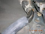
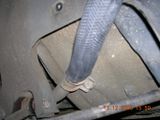
Anyway, today I did some work on, and nearly finished, the piping. It's ended up much simpler than I expected. I have used the stock rubber hose, cut up a bit and with some stainless steel 90 degree bends. I will be attaching a bleed fitting to the intentionally created high-points to prevent airlocks. I have pictures and I will post tomorrow
User avatar
Malcolm
Toyspeed Member
 
Posts: 4631
Joined: Tue May 14, 2002 1:01 am
Location: Auckland

Postby Ae92typeX » Wed Dec 14, 2005 10:31 am

looking pretty good so-far!, Im following with interest...although I just finished all the pannel and paint in that area of mine so I dont think my aw will be getting any big alteration for some time.
Cant believe im still a member here.

http://toyspeed.blakjak.net/profiles/profile.php?id=113
User avatar
Ae92typeX
Toyspeed Member
 
Posts: 2639
Joined: Fri May 17, 2002 11:00 pm
Location: North Shore

Postby Malcolm » Wed Dec 14, 2005 8:04 pm

here's piping, from yesterday. Both sides are pretty much identical so I'll only post pics of one side...
Image Image Image Image

here's a shot of everything sort of together
Image

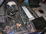
this is what the air sees after it passes through the radiator, looking out at the vent. The gap there is only because he frame isn't welded into place yet.
Image

I also mounted the w/a pump on the bumper beam today. This pump is absolutely massive compared to the old subaru pump
click here to see the two side by side
Image Image

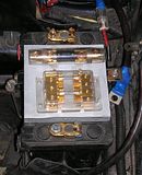
And finally, I made this little thing to mount my fuses on. Big one goes in the power cable from battery -> starter, the one with the 4 individual fuses will go to the amps(x2), fuel pump, and the w/a pump
Image
User avatar
Malcolm
Toyspeed Member
 
Posts: 4631
Joined: Tue May 14, 2002 1:01 am
Location: Auckland

PreviousNext

Return to General Car Discussion

Who is online

Users browsing this forum: Google [Bot] and 6 guests

cron