2JZGTE ECU and FPC Output

The place for all technical car discussions. If you haven't already, read our Disclaimer first!

Moderator: The Mod Squad

2JZGTE ECU and FPC Output

Postby MrOizo » Thu Oct 28, 2010 10:58 pm

(I have tried other forums but they dont seem to be interested :? I know there are a few clued up people on here that might know whats going on)

I have had a bit of reworking going on for the fuel pump and have got a kit to sense any voltage on the FPC wire to switch a relay. This is to do away with the FP ECU and only having one speed on the Bosch 044

I have been trying to test it but i am getting no voltage from this wire. Everywhere i have read says this should put out a 3-5v signal.

When the key is turned to ON (or Start), i should have 5v and then 0v after a few seconds if the engine hasnt started yet. I have 0v all the time.

Is there something that i might have forgotten to plug in to not have any voltage on this wire? Hmmmmm

--------------------------

I should have added that i have no FP ECU which is the whole reason for coming up for a solution for no FP ECU.

I have a simple Jaycar kit which detects a pulsed frequency and turns a relay on.

I had a play today and have taken these photos:

IGN OFF, connected to Earth and FPC from ECU
Image

IGN ON, connected to Earth and FPC from ECU
Image


IGN OFF, connected to 12vand FPC from ECU
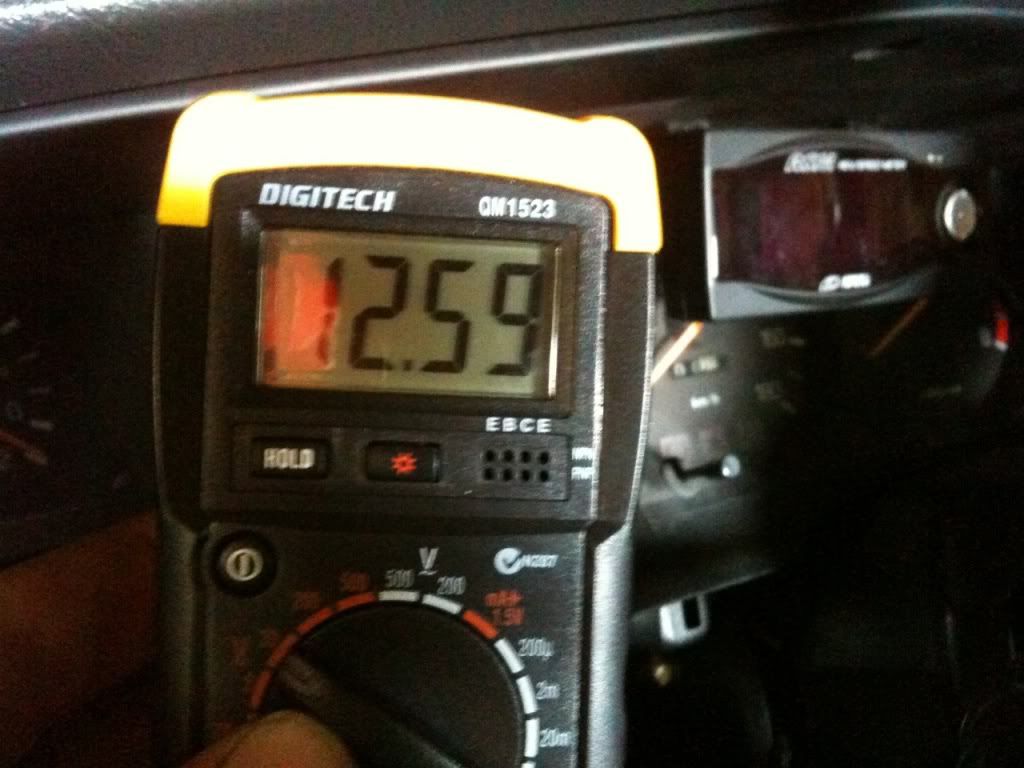
Image

IGN ON, connected to 12vand FPC from ECU
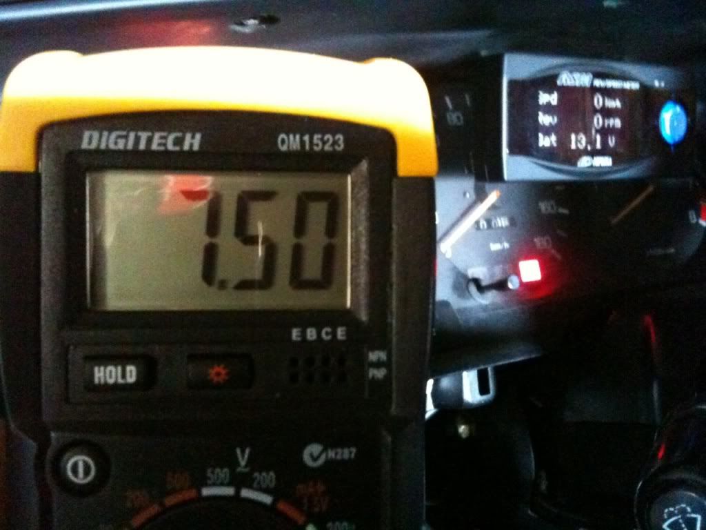
Image

Any suggestions as to whats going on here? I am starting to think its the ECU...
User avatar
MrOizo
Toyspeed Legend
 
Posts: 6658
Joined: Thu May 16, 2002 9:26 pm
Location: Onehunga, Auckland

Postby 1hypo3 » Fri Oct 29, 2010 8:25 am

Might need a bit more info on this jaycar kit you have?

To check if its the way you have wired in this kit or if its faulty , disconnect the output wire from ecu and check the signal, if its a pulsed signal you will need an oscilloscope that way you will know if its the kit or the ecu.
1hypo3
Toyspeed Member
 
Posts: 57
Joined: Sat Mar 08, 2008 6:09 pm
Location: New Plymouth

Postby gasman » Fri Oct 29, 2010 9:07 am

I thought you could get away with not running the FP ecu and just live with a noisey pump and a engine check light on.
"What can possibly go wrong?"
User avatar
gasman
Toyspeed Member
 
Posts: 999
Joined: Tue May 04, 2004 11:29 pm
Location: lower hutt, wellington

Postby MrOizo » Fri Oct 29, 2010 9:08 am

1hypo3 wrote:Might need a bit more info on this jaycar kit you have?

To check if its the way you have wired in this kit or if its faulty , disconnect the output wire from ecu and check the signal, if its a pulsed signal you will need an oscilloscope that way you will know if its the kit or the ecu.


Thanks for replying.

I havent got the FPC output hooked up anymore.
I get 0v with IGN OFF, and 0.08v with IGN ON.

The signal from the ECU is apparently a PWM signal and it should read 0v, 2.5v, 5v depending on duty. I have a PWM kit here and i tested the relay kit and had it switching at 1.80v from the PWM. .

I should still be able to read voltage right?

Cheers.
User avatar
MrOizo
Toyspeed Legend
 
Posts: 6658
Joined: Thu May 16, 2002 9:26 pm
Location: Onehunga, Auckland

Postby MrOizo » Fri Oct 29, 2010 9:12 am

gasman wrote:I thought you could get away with not running the FP ecu and just live with a noisey pump and a engine check light on.


I am trying to do that but want the pump to only switch on with engine running. had it on the M-REL last time - not the safest :)
User avatar
MrOizo
Toyspeed Legend
 
Posts: 6658
Joined: Thu May 16, 2002 9:26 pm
Location: Onehunga, Auckland

Postby gasman » Fri Oct 29, 2010 12:11 pm

couldn't you set up a fuel pump relay and set it to click of when the alternator charge light comes on? and to click on during cranking by tapping into the starter solenoid power feed?
"What can possibly go wrong?"
User avatar
gasman
Toyspeed Member
 
Posts: 999
Joined: Tue May 04, 2004 11:29 pm
Location: lower hutt, wellington

Postby MrOizo » Fri Oct 29, 2010 2:06 pm

gasman wrote:couldn't you set up a fuel pump relay and set it to click of when the alternator charge light comes on? and to click on during cranking by tapping into the starter solenoid power feed?


Thats been thought of but not too keen on that - should be no reason that the FPC output isnt working other than its stuffed. I thought i might not have had something plugged in for it to do that but cant find anything.
User avatar
MrOizo
Toyspeed Legend
 
Posts: 6658
Joined: Thu May 16, 2002 9:26 pm
Location: Onehunga, Auckland

Postby whynot » Fri Oct 29, 2010 9:29 pm

so if I understand this right you are looking for a voltage coming out of this wire on the ecu? My understanding was that most outputs from an ecu are ground outputs in which case you will only get a reading when you put your multi meter from positive 12v to the wire and trigger the output.
"You can't do it like that!." "Why not?"
User avatar
whynot
Toyspeed Member
 
Posts: 418
Joined: Thu Apr 23, 2009 6:56 pm
Location: Melbourne

Postby MrOizo » Fri Oct 29, 2010 9:38 pm

whynot wrote:so if I understand this right you are looking for a voltage coming out of this wire on the ecu? My understanding was that most outputs from an ecu are ground outputs in which case you will only get a reading when you put your multi meter from positive 12v to the wire and trigger the output.


Ken (Kinloud) and i have been over the diagram below and he has told me that it indeed supplies voltage due to the type of transistor in the circuit (PNP?).
(Its the Violet-White wire / A22)

When i turn the ignition ON, i get about 0.08v on that wire - is that just from the ECU having power?

Thanks for help so far.
Cheers.


Image
User avatar
MrOizo
Toyspeed Legend
 
Posts: 6658
Joined: Thu May 16, 2002 9:26 pm
Location: Onehunga, Auckland

Postby whynot » Fri Oct 29, 2010 11:30 pm

if that output has a resistor in it as shown it may be making it difficult to get a certian reading out of it. not sure how it works but it may also be a 5 volt output in releation to the 12 volt rail of the ecu, when you have it switched on and take the reading (as in pic) it shows 7.5 volt. if your supply is 12.5 then there is your 5 volt difference you are expecting. what you may be able to do is put a resistor on the output and connect it to ground then build a voltage sensing switch (jaycar do them ) and use the signal between the resistor and ecu pin out to trigger it.

basically you want to build a voltage divider using an external resistor and the one in the ecu and a circuit than can tell the difference between 7.5 and 12 volt im pretty sure you need a voltage divider as the sensing switch looks for the voltage difference to ground not supply.

Not sure if this will work so would pay to run this idea past Ken and come back with any questions or flaws about this
"You can't do it like that!." "Why not?"
User avatar
whynot
Toyspeed Member
 
Posts: 418
Joined: Thu Apr 23, 2009 6:56 pm
Location: Melbourne

Postby MrOizo » Fri Oct 29, 2010 11:40 pm

Thanks again for some input - having breakfast with him tomorrow so will run it past him then :)

I think i am the only one having this issue which makes me think that i might have wired up the FPC wire wrong when i did the swap and something has gone wrong?.

A guy from supramania did the 2JZ swap and did this mod as follows:

I don't have my notes with me, but you use an NPN transistor with the B terminal connected to the 2JZ FPC terminal, C terminal to the ground side of the COR coil, and the E terminal is grounded to the chassis. The positive side of the COR coil goes to switched a 12V source. You should have a diode across the relay coil to prevent a current surge in the backwards direction. What this does is when the 2JZ ecu thinks the pump should be running it sends a 3-5V signal to the FC terminal. The transistor sees this and closes the circuit for the relay to ground. Mine has works flawlessly since day 1 and its built into my adapter harness. The total cost is under a buck and much more elegant than other solutions I've seen. HTH
User avatar
MrOizo
Toyspeed Legend
 
Posts: 6658
Joined: Thu May 16, 2002 9:26 pm
Location: Onehunga, Auckland

Postby whynot » Fri Oct 29, 2010 11:50 pm

don't see why that wouldn't work I tried a similar arrangement on my ecu but I think it failed due to me trying to run the vvt and check engine light on the same output, there was some back feed from the lamp check circuit and I think it was enough to hold the vvt on or something (nearly did my head in that problem)

anyway what he has done would usually be done to a low voltage low current output often straight out of a microchip which seems to be what your test meter results are suggesting you have
"You can't do it like that!." "Why not?"
User avatar
whynot
Toyspeed Member
 
Posts: 418
Joined: Thu Apr 23, 2009 6:56 pm
Location: Melbourne

Postby 1hypo3 » Sat Oct 30, 2010 7:57 am

you cant use a multimeter on a pulsed circuit as it wont give accurate results, you need to use a scope.
In saying that i suspect there maybe be something wrong internally with that circuit. If you are confident enough you can trace the circuit and test the transistor with a scope and check the resistor with the ohm meter.
1hypo3
Toyspeed Member
 
Posts: 57
Joined: Sat Mar 08, 2008 6:09 pm
Location: New Plymouth

car

Postby docTRD » Sat Oct 30, 2010 2:51 pm

Hey Adrian, if you want a spare 2jzgte ecu to try I have one, its an aristo one. Ive mucked around with FPC before also and they can be quite confusing. Ive got a scope you could use to see whats coming from the FPC as if it is a PWM signal a multimeter will not read it properly as its expecting a sine wave. cheers
Daily : st191 corona liftback mmm room
Project : Jzx90 mark2 Tourer V
--- wtd: corolla GT ae92 sedan ---

"Mum i knw its another wreck, i only got it so i can put the seats in the lounge" YEAH RIGHT
User avatar
docTRD
Mo Joe
 
Posts: 664
Joined: Wed Nov 17, 2004 12:24 am
Location: Auckland

Re: car

Postby MrOizo » Sat Oct 30, 2010 4:24 pm

whynot and 1hypo3 - thanks for your input - going to sort it out soon. Will have a test of the resistance soon.


docTRD wrote:Hey Adrian, if you want a spare 2jzgte ecu to try I have one, its an aristo one. Ive mucked around with FPC before also and they can be quite confusing. Ive got a scope you could use to see whats coming from the FPC as if it is a PWM signal a multimeter will not read it properly as its expecting a sine wave. cheers


That sounds like a plan, cheers.

If youre free tomorrow could i get it then? The FPC output should still be the same right?

Right now I have the ECU apart and going to have a lookie at it - who knows what im looking for :)
User avatar
MrOizo
Toyspeed Legend
 
Posts: 6658
Joined: Thu May 16, 2002 9:26 pm
Location: Onehunga, Auckland

Postby MrOizo » Sat Oct 30, 2010 6:00 pm

Weeeeeeeeeeeeeeeeeeeeeeeeel.....

Been going over this since i posted last and i have managed to find this:

Image

Its Red-Red-Gold-Gold which reading up charts it should be 2.2 Ohm.

I measured resistance across it and its reading 3.2 Ohm (well i think i did it right :P)

Was hard to tell if this was on the FPC circuit.
I found one that was on the DI (other fuel pump wire [diagnostics?]) but I keep losing the FPC tracks on the PCB.

Thinking about replacing - anything i should consider before doing such a task?

Cheers.
User avatar
MrOizo
Toyspeed Legend
 
Posts: 6658
Joined: Thu May 16, 2002 9:26 pm
Location: Onehunga, Auckland

Postby sergei » Sat Oct 30, 2010 6:07 pm

Cooked resistor is just a symptom.
You will need to replace the transistor (T707) that drives that circuit.

If you can't find exact one, I can help you find equivalent.

Just reread your post and before replacing stuff, make sure it is the right transistor.
From circuit point of view the transistor should be directly connected to the pin. Crude way to find out is set the multimeter to Ohm meter mode and chuck one of the probes on the pin, and keep probing every collector (C) until you find one close to 0 Ohm.
Last edited by sergei on Sat Oct 30, 2010 6:37 pm, edited 2 times in total.
User avatar
sergei
Mad Russian
 
Posts: 8406
Joined: Wed May 15, 2002 12:06 pm
Location: North Shore

Postby MrOizo » Sat Oct 30, 2010 6:12 pm

sergei wrote:Cooked resistor is just a symptom.
You will need to replace the transistor (T707) that drives that circuit.

If you can't find exact one, I can help you find equivalent.


Wow you're a legend. I have a feeling this was cooked from when I wired first - following some on elses instructions.

Had a read up and said if a transistor was wired wrong it would most likely need to be replaced. How do i find which one on the board it is? and how can i even tell if this resistor is in the FPC circiut?
User avatar
MrOizo
Toyspeed Legend
 
Posts: 6658
Joined: Thu May 16, 2002 9:26 pm
Location: Onehunga, Auckland

Postby sergei » Sat Oct 30, 2010 6:36 pm

MrOizo wrote:How do i find which one on the board it is? and how can i even tell if this resistor is in the FPC circiut?


sergei wrote:From circuit point of view the transistor should be directly connected to the pin. Crude way to find out is set the multimeter to Ohm meter mode and chuck one of the probes on the pin, and keep probing every Collector (C) until you find one close to 0 Ohm.
User avatar
sergei
Mad Russian
 
Posts: 8406
Joined: Wed May 15, 2002 12:06 pm
Location: North Shore

Postby MrOizo » Sat Oct 30, 2010 6:46 pm

ok thanks.

Will look into that later tonight.

Cheers.
User avatar
MrOizo
Toyspeed Legend
 
Posts: 6658
Joined: Thu May 16, 2002 9:26 pm
Location: Onehunga, Auckland

Next

Return to Tech Questions

Who is online

Users browsing this forum: Google [Bot] and 13 guests